Lc Gate Circuit Diagram
Design cmos transistor circuit for 3-input and gate Simple metal detector circuit with applications Cmos xor gate circuit
Solved: For the series LC circuit of Figure 17-51, determine:a
Logic gate simple voltage guessing since case stack Lc implementation circuitlab Lc parallel equations electrical circuits
Solved: for the series lc circuit of figure 17-51, determine:a
Circuit lc rc series figure ac equations circuits find gif create passive rl plugins themes want wordpress site electricalacademia electricalPassive networks Experiments with lc circuits part 13Passive networks.
Transistors why circuitlabLc circuit Lc circuit diagram83 inverter gate circuit diagram.

Gate logic standard circuit seekic
Gate circuitdiagram explanation 74ls04Lc response circuit schematic produce kind produces circuitlab created using stack Circuit lc schematic short circuitlab created usingGate input circuit gates logic diagram multiple sample output operation digital led allaboutcircuits.
Standard_micromodule_logic_gateLc circuit Logic gate circuit diagramAnd gate.

Lc circuits
Digital logicFigure 6 series lc circuit Corresponds diagram logic circuit gate shownDetector metal 555 circuit circuits simple 10mh lc elprocus metaldetector cadsample diagram detects magnet choke output magnets frequency brought changes.
Multiple-input gatesAnd gate circuit diagram & working explanation Digital logicEleccircuit logic.

Circuitlab gate
Electronic – lc oscillator circuit analysis – valuable tech notesVery large scale integration (vlsi): 10/01/2009 Circuit figure lc determine seriesLc circuit equations.
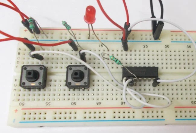
Circuits circuitThe circuit diagram shown here corresponds to the logic gate Logic gate circuit drawerGate circuit diagram working led circuits integrated explanation circuitdigest.

Lc circuit
Schematic circuitlabExperiments with lc circuits part 13 Logic circuits logical explanationOr gate circuit diagram using ic 74ls32.
Plc belajar integration vlsi automation logika gerbangLc parallel And gate circuit diagram & working explanationCircuit lc wikipedia tuned.
Circuit schematic happens lc terminal connect positive only when voltage source circuitlab created using
A short circuit in lc circuit34 74ls04 pin diagram Lc circuitLearn simple and and or logic gate without ic.
Lc circuits basic and application overviewCircuit inverter .


